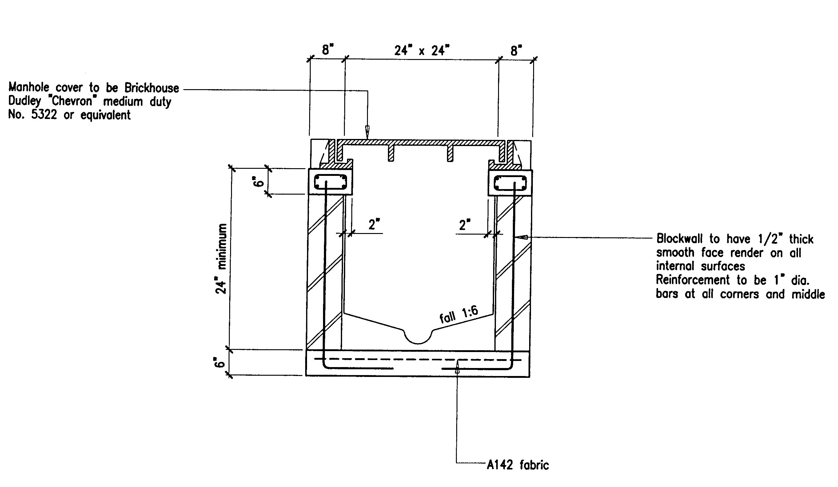
rcc drain section drawing
The scale is 38 inches is equal to one foot. WIDE 28 136 50 31 50 3314 5455 40 27 50 ROAD.

Planndesign Com On Twitter Autocad Drawing Of A Typical Drain Detail Near Column And Over Column Footing Showing Construction Detail With R C C Structure Through A Detailed Section Workingdrawing Cad Caddesign Caddrawing Freecaddrawing
Sketch the drawings and detail as per the requirements.

. The backfill is horizontal. RCC Drain Box Section CAD Drawing DWG File RCC box drain under fluctuating depth of a road embankment CAD drawing which consist 100mm PCC size 300 mm bottom slab size and 300 mm wall thick size with all reinforcement detail. Dimensions are not to be scaled and only written dimension are to be followed.
The proposed subproject includes Construction Improvement of 7 Nos. Necessary precaution shall be taken while excavating the foundation near by the drain. Road drainage design has as its basic objective the reduction andor elimination of energy generated by flowing water.
Intercepting drains pipe drains in hill roads details of drains in cutting embankment typical cross sections 8. Autocad drawing of Typical basement drainage catch basin pipe detail. Report any discrepancies.
These drains have holes and permit the collected water to get discharges into another drainage system. It uses the class D concrete. The engineer approval of the shop drawing must be obtained prior to commencement of work.
Typical reconstruction of slab drain 600 mt. The cross section of the column will show the dimension of the column which is equal to 25 feet and the other column is 3 feet. RCC Manhole Systems available in cylindrical conical and cuboid shapes have successfully replaced the old traditional manholes made from bricks which were time consuming and structurally weak for providing access to telecommunication infrastructure and sewerage system.
Secondary Drains totalling 3736 km 2 Nos. Unit weight of wall 23 knm3 cement concrete block unit weight of rcc 25 knm3. RCC Retaining Wall PCC Wall Lined Drain Approach Slab should be provided where Cross Road exists BC DBM Granular Base Granular Sub Base for Drainage Separation layers Figure.
The notes in this drawing shall be read in conjunction with all relevant drawing pertaining to the bridge. Retaining wall Design Design example-1 Design a cantilever retaining wall T type to retain earth for a height of 4m. Drawing showing drainage these arrangements.
PROPOSED RCC Rcc Slab Fe 415 CC mix 100mm Plastering t2mm 150mm FCC 3 with 40mm. M-15 025 205 sand pcc. Cross-drain structures are used below the road embankment to pass the watercourse.
Trench Drain - 12 Inch Deep. RCC Standard Drawings Drainage Author. 6 - Typical Cross section at Viaduct Portion Full Height Intersection with Kalyani Expressway Ch.
Now let us examine the cross-section for the column. Thank you for downloading the AutoCAD file and other CAD program from our website. We offer a qualitative range of Storm Drain Covers which is fabricated using high grade material and is known for its high bond strengthAvailable at industry leading prices these RCC Drain Covers find application in the installation of larger pipes and are also used for sewerage pipes and storm water drainage.
Drawing accommodate double basement section shows drainage flowing system from upper basement to lower basement through 100 mm dia pipe and going to catch basin. I Sub Drawn By Executive Engineer R NH. RCC Manhole System.
General notes for rcc construction work a. The density of soil is 18kNm3. Suitable construction keys drainage facilities tile drains and weep holes as shown in the drawing.
The drawings should be read in conjunction with other relevant drawings and all relevant sections of the specifications. Tertiary Drain totalling 0106km within Barguna Pourashava area under Barguna district. We are engaged in offering RCC Nali Gutter which are durable in nature and have high strength.
36 50 15 8530 In PROPOSED WIDE 50 ROAD 21 50 50 40 130ö COMPOUND WALL 18M HIGH DRAIN 100 50 28 WITH STEEL GRATING RCC SLAB CULVERT ROAD SIDE DRAIN 114-9 14 50 41 NATURAL DRAIN NATURAL DRAIN CH. Precast RCC Drains We are one of the topmost manufacturers and supplier of a wide range of Precast RCC. DRAIN SECTION DETAILS SCALE.
Moreton Bay Regional Council Created Date. Section square return riding return proposed widening ref. Diploma holders in Civil Engineering will be required to supervise RCC Construction and fabrication.
The drainage chamber box RCC construction drawing that shows the hume pipe connected the cages and fitted into the mould as per the size of the pipe RCC wal with 12 mm THK inside plaster and all measurement detail. DETAILS OF RCC DRAIN Type I T10 T10200 1200 150 150 1200 136 Screed375 Concrete T10200 T10300 12419mm Concrete wall DETAILS OF. This structure has been designed for the following nominal loads.
It is manufactured at our infrastructure using the optimum quality raw material and the modern. Trench Drain - 6 Inch Deep. For reinforcement other details refer standard plan for highway bridges wit r cc slab type super structure vol- ii issued by ministry of surface transport road wing new delhi.
Depth is 6 inches and for the second step the depth is 6 inches. Before starting any work the contractor has to submit shop drawings showing all details needed. Span plan 110 025 240 sand pcc.
Our entire product line is functionally advanced in nature and has high compressive strength. RCC DESIGN AND DRAWINGS L T P 5 - 2 RATIONALE This subject is an applied engineering subject. Unless otherwise specified all dimensions in millimeter mm and all levels are in meter m.
Trail Culvert and Rip Rap Apron. Iii The challenge for the subproject is that the drainage components are implemented in the. 3620 BC DBM Granular Base Granular Sub Base for Drainage.
The destructive power of flowing water as stated in Section 322 increases exponentially as its velocity increases. Engineering or Building Services.